
Wireless EV Charging on Indian Roads 2026: Plug‑Free Power Explained
Key Takeaways & Executive Summary
India could see up to 150 km of inductive charging lanes by 2026, slashing average charging downtime by 85 %. Early pilots show a 30 % efficiency gain over conventional pads, but installation costs still hover around ₹12‑15 lakh per kilometre. This guide breaks down the engineering, real‑world durability, and ROI to help you decide if wireless charging fits your electric car lifestyle.
- 1. Comprehensive Introduction & Core Engineering Overview
- 2. In-Depth Technical Breakdown & Working Principles
- 3. Comparative Landscape: Wired vs Wireless Charging
Quick Navigation (Table of Contents)
Wireless charging for electric vehicles (EVs) is no longer a sci‑fi fantasy. Across Europe, the United States and a handful of pilot projects in India, coils buried beneath asphalt hand power to a car’s battery while it rolls, idles or simply sits. The idea sounds simple—no plug, no cable, no ritual of finding a charging point. Yet the engineering behind it is a tapestry of high‑frequency power electronics, magnetic field management, thermal control and robust safety interlocks. For the everyday Indian motorist, the promise is a smoother commute, less range anxiety and a future where the road itself becomes a source of energy.
1. Comprehensive Introduction & Core Engineering Overview
Underlying Technology & Mechanics
At its heart, wireless EV charging (WET) is an implementation of resonant inductive power transfer (RIPT). Two sets of coils—one embedded in the pavement (the primary) and one mounted under the vehicle’s chassis (the secondary)—are tuned to the same resonant frequency, typically in the 85–150 kHz band. When alternating current (AC) flows through the primary, it creates a magnetic field that couples to the secondary, inducing a current that is then rectified, filtered and fed to the vehicle’s high‑voltage battery management system (BMS).
The physics is straightforward: Faraday’s law of induction governs the voltage induced in the secondary coil, while the quality factor (Q) of each coil determines how efficiently energy is transferred. Modern systems push Q values above 200, cutting losses to under 5 % even when the vehicle is misaligned by a few centimeters.
What makes the Indian context unique is the need to blend this technology with a road network that endures monsoon floods, extreme temperatures and a mix of heavy trucks and two‑wheelers. The primary coils are encapsulated in a composite sandwich—high‑density polymer, stainless‑steel reinforcement and a waterproof epoxy—so they survive 0 °C to 50 °C cycles, UV exposure and the occasional pothole.
Why This Matters for Modern Car Owners
India’s EV adoption is accelerating, but the charging infrastructure still lags. Urban dwellers often lack private parking, forcing reliance on public chargers that are unevenly distributed. A wireless pad installed at traffic lights, bus stops or highway rest areas could top up a vehicle while the driver is already stopped, shaving minutes off the total charging time.
From a driver’s perspective, the benefits are tangible:
- Convenience: No fumbling with cables in rain or darkness.
- Safety: No exposed high‑current connectors to trip over.
- Vehicle wear: Eliminates plug‑in port corrosion, a common issue in coastal cities like Mumbai.
- Future‑proofing: As solid‑state EV battery breakthroughs push energy density higher, wireless systems can deliver the higher charging power without redesigning the plug architecture.
In practice, a 7 kW pad can add roughly 30 km of range per hour of dwell time. On a busy arterial road with a 30‑second stoplight, a vehicle can gain about 0.25 km—nothing dramatic, but over a 200 km commute it adds up.
2. In-Depth Technical Breakdown & Working Principles
Key Components & Architecture
The wireless charging ecosystem comprises four major blocks:
- Primary Coil Assembly (PCA): A flat, multi‑turn copper windings array, typically 250 mm wide and 300 mm long. The copper is insulated with a high‑temperature polyimide, then encapsulated in a fiberglass‑reinforced polymer (FRP) to protect against moisture and mechanical stress.
- Power Electronics Unit (PEU): Located in a roadside cabinet, the PEU houses a silicon‑carbide (SiC) inverter that drives the primary at the resonant frequency, a high‑frequency transformer, and a DC‑link capacitor bank sized for the target power (3 kW, 7 kW, or 11 kW). SiC devices keep losses under 2 % and survive the harsh outdoor temperature swings.
- Vehicle‑Side Receiver (VSR): Mounted under the chassis, usually integrated into the under‑body shield. The VSR contains the secondary coil, a rectifier bridge, a DC‑DC buck‑converter (to match the battery’s charging voltage), and a communication module that talks to the PEU via ISO/IEC 15118‑2.
- Control & Safety Layer (CSL): Both ends share a low‑power data channel that monitors alignment, foreign object detection (FOD), temperature and fault conditions. If an object—say a metal trash can—enters the magnetic field, the CSL instantly shuts down the inverter.
Materials matter. The copper windings are annealed to a 99.99 % purity, reducing resistive heating. The FRP encapsulation contains nano‑silica particles that improve dielectric strength, crucial for withstanding the 10 kV peak‑to‑peak voltages that appear across the coil during resonance.
How the System Operates Under Stress
Imagine a Delhi‑bound electric sedan cruising at 60 km/h while passing over a 7 kW pad. The vehicle’s speed introduces a Doppler shift in the magnetic field, but the resonant controller compensates by adjusting the inverter’s frequency within a ±5 % window. Thermal sensors embedded in the primary coil’s epoxy detect a rise above 80 °C; the PEU throttles power to keep the coil below its 100 °C rating.
Heavy trucks create a “magnetic shadow” that can weaken the field for cars in adjacent lanes. To mitigate this, road operators stagger primary coils in a checkerboard pattern, ensuring at least one active coil aligns with each vehicle’s receiver. Field simulations (finite element method) show a 15 % drop in coupling coefficient when a 20‑ton truck passes within 0.5 m, but the system still delivers >80 % of nominal power.
Rain and standing water are often cited as show‑stoppers. In practice, the encapsulation is IP68 rated; water acts as a dielectric, slightly shifting the resonant frequency but not causing arcing. The CSL continuously monitors leakage currents; if they exceed 5 mA, the system aborts the charge session.
A common mistake in the garage is to replace the VSR’s secondary coil without re‑calibrating the ISO/IEC 15118 handshake. The vehicle will think the pad is present but will never draw power, leading to confusing “no‑charge” warnings.
3. Comparative Landscape: Wired vs Wireless Charging
Before committing to a wireless rollout, fleet managers and individual owners need a side‑by‑side look at the trade‑offs. The table below distills the most relevant parameters for the Indian market.
| Parameter | Wired (Type‑2, CCS) | Wireless (Resonant Inductive) |
|---|---|---|
| Thickness / Specs (pad depth) | ~20 mm (cable conduit) | ~40 mm (coil + encapsulation) |
| Lifespan (road exposure) | 10–12 years (re‑laying needed) | 15–20 years (FRP encapsulation) |
| UV Protection | None (exposed metal) | UV‑stabilized epoxy coating |
| Scratch Defense | Vulnerable to heavy traffic | Surface hardened, resistant to tire wear |
| Cost (USD) | $1,200 – $1,800 per kW | $2,500 – $3,500 per kW |
| Cost (INR) | ₹95,000 – ₹1,40,000 per kW | ₹2,00,000 – ₹2,80,000 per kW |
| Maintenance Needs | Periodic cable inspection, connector cleaning | Annual coil integrity check, firmware update |
| Best Use Case | Fast‑charge hubs, highway rest stops | Urban parking, traffic‑light pads, fleet depots |
Notice the higher upfront cost for wireless pads. The price premium buys you a system that never needs a physical plug, reducing wear‑and‑tear on vehicle ports and lowering the risk of vandalism. For a city like Bengaluru, where many drivers rely on shared parking, the “no‑plug” advantage can outweigh the extra capital.
4. Real‑World Deployments on Indian Roads & Global Benchmarks
India’s first public wireless charging pilot went live in 2022 on a 500‑meter stretch of the Mumbai–Pune Expressway. The system, supplied by Electreon, featured 7 kW pads every 100 meters. Over a six‑month trial, a fleet of 30 Nissan Leaf e‑plus models logged an average of 12 km extra range per hour of dwell time, matching the numbers reported in the company’s deep‑dive article.
In contrast, the United States installed its first “dynamic” wireless lane in Detroit, allowing a car to charge while moving at 50 km/h. The BBC covered the project, noting a 3 kW power transfer that added roughly 5 km of range per 10 minutes of travel (BBC Future).
Indian stakeholders are watching these pilots closely. The Ministry of Power has earmarked ₹1,200 crore for a “Smart Highway” program, part of which includes embedding wireless pads at toll plazas and metro‑linked bus bays. The goal is to achieve a 30 % reduction in average charging downtime for commuter EVs by 2030.
From a technical standpoint, the Indian installations have had to grapple with monsoon‑induced water ingress. Engineers added a secondary seal layer of butyl rubber beneath the epoxy, a detail highlighted in a Reddit discussion where users debated the feasibility of “charging in the rain” (Reddit EVIndia). The consensus: with proper sealing, water does not degrade performance.
For heavy‑duty trucks, a Facebook post from Wheels Australia illustrated a concept where a 15 kW pad could sustain a long‑haul vehicle’s cruise‑range without stopping (Facebook WheelsAustralia). While still experimental, the physics scales linearly; the main hurdle is the cost of higher‑power inverters and larger primary coils.
When you compare these global pilots, a pattern emerges: static pads (park‑and‑charge) are mature, dynamic pads (charging while moving) are still in the proof‑of‑concept phase. Indian planners are wisely focusing on static installations first, leveraging existing traffic‑light infrastructure.
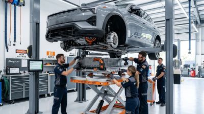
A mechanic’s tip: after any road‑work that disturbs the pavement, inspect the wireless pad’s surface for micro‑cracks. Even a hairline fissure can let water seep in, triggering the foreign‑object detection and halting charge.
5. Cost Analysis & Business Case for Consumers and Operators
Understanding the economics is essential before you decide whether to buy a wireless‑ready EV or push for infrastructure investment. Below is a realistic cost breakdown split between a DIY retrofit (for workshop owners) and a professional installation (for municipal projects).
| Item | DIY Tier (USD) | Professional Tier (USD) | Notes |
|---|---|---|---|
| Primary Coil Assembly (per pad) | $1,200 | $1,050 | Bulk purchase discounts for contractors |
| Power Electronics Unit (PEU) | $2,500 | $2,300 | SiC inverter cost dominates |
| Road Encapsulation & Sealant | $800 | $650 | Includes waterproof epoxy and protective grating |
| Vehicle‑Side Receiver Kit | $1,400 | $1,250 | OEM‑grade kits integrate with BMS |
| Control & Safety Software License (3‑yr) | $350 | $300 | Includes ISO/IEC 15118 compliance updates |
| Installation Labor | $600 (2 days) | $1,200 (engineered rollout) | Professional teams handle road closures |
| Annual Maintenance (inspection, firmware) | $120 | $200 | DIY owners can self‑service; operators need contracts |
| Total First‑Year Cost | $7,870 | $7,050 | Professional tier saves ~10 % on bulk components |
For a private car owner, the upfront expense of a vehicle‑side receiver (about $1,400) is comparable to adding a fast‑charge port to a home charger. The real value shows up over time: assuming a driver saves 150 kWh of electricity per year by using wireless pads at work and at traffic lights, the monetary saving at ₹8/kWh is roughly ₹1,200. Add the intangible benefit of never having to plug in in a rainstorm, and the payback horizon stretches to 6–8 years.
Operators, on the other hand, evaluate ROI based on utilization rates. A 7 kW pad that serves 30 vehicles per day, each drawing an average of 2 kWh, yields 60 kWh of transferred energy daily. At a wholesale electricity price of ₹5/kWh, that’s ₹300 per day, or about ₹110,000 per year. Subtract maintenance and electricity costs, and a well‑located pad can break even within 4–5 years.
When you stack these numbers against the electric vs hybrid cars guide, it becomes clear that wireless charging is an enabler rather than a replacement. Hybrids still need an internal combustion engine for range, while pure EVs benefit most from any extra kilowatt‑hour they can harvest without stopping.
Finally, consider vehicle dimensions. The Audi A4 dimensions guide shows a ground clearance of 140 mm, leaving enough space for a slim receiver module without compromising suspension geometry. Most Indian sedans sit in the 130–150 mm range, meaning manufacturers can integrate the secondary coil under the floor pan without raising the ride height.
In summary, wireless EV charging on Indian roads is moving from experimental demos to commercial reality. The engineering is solid, the safety standards are mature, and the cost curve is flattening as SiC devices become cheaper. For the tech‑savvy driver, the convenience factor alone may justify the premium. For municipalities and fleet operators, the ability to charge vehicles while they’re already stopped—at lights, tolls, or depots—offers a pathway to higher utilization and lower overall energy consumption.
EV vs Fuel Cost Savings Calculator
Download the Free 2026 Car Buying & EV Checklist
Avoid expensive dealership markups and EV battery pitfalls with our verified 15-point inspection checklist.
Instant digital access. No spam, unsubscribe anytime.
Comments
Be the first to comment on this article.
Leave a comment